
|
Interior View of Production Unit |
|
Copyright 2007 by John Blankenbaker |
|
|

|
The view of the interior shows the arrangement of the parts. Across the bottom was the logic board with the 132 integrated circuits on it. The two power supplies, one for +5 volts and one for –12 volts, were along the rear and overhung the logic board. Enough power was dissipated in the unit to require a small cooling fan seen at the left rear. The air stream from this was directed at the two MOS shift registers used for the memory. The air, after passing over the power supplies, exited in back of them. The front panel had the lights and switches which were connected by wires to the logic board. Incandescent lights (T-1 bulbs) were used instead of LEDs as they were brighter. The case itself was a modified Bud "Grand Prix" unit made from steel. This provided excellent protection except for the switches in the front. The clock of about 1 MHz was generated by a multivibrator. Several cosmetic and small technical changes were made in going to the production units from the prototype unit. The use of a red pushbutton to store data in the memory was abandoned. Instead a toggle switch was installed to lock the memory against changes from the front panel. Legends were redesigned and relocated for better visibility. A slot was installed in the front panel for a possible punched card input.
|
Technical |

|
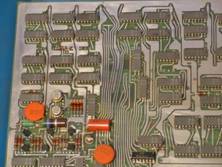
The view here is of the left rear corner, just under and to the front of the fan. On the left, about a third of the way up, are the two MOS shift registers used for the memory. These were very reliable and I have no recollection of having to replace one. As an example of the conservative design, the power could fall as low as 70 volts AC and the computer would still work. |